Quick Start: Connecting a Smart Device to EnOS™ Cloud
This section helps you quickly learn how to connect a direct-connecting device to the EnOS Cloud, how to send device telemetry, and how to check the device communication status from the EnOS Management Console.
About the Scenario
For information about the connection scenario of this task, see “Scenario 1.1” in Device Registration Methods.
About This Task
Let us take the household PV inverter connection as an example. The inverter device triple is burned into the inverter during manufacturing. After you power on and connect the inverter to the network, the inverter is connected to the IoT Hub based on the device triple authentication. The overall connection scenario is shown below.
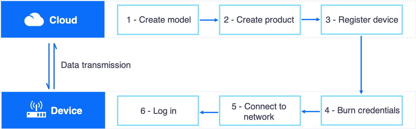
The procedure has the following steps:
- Create a device model for the inverter.
- Create a product for the inverter.
- Register the inverter.
- Configure the storage policy for the measurement point data.
- Use the EnOS SDK to simulate the inverter to send data.
- Check the device communication status.
- View the device data.
- Use the online debugging tool to set the measurement point value
Step 1: Create a Device Model
This step assumes that there is no existing device model that can be reused. Create a new model named Inverter_Demo with the features defined as per the below.
| Feature Type | Name | Identifier | Data Type | Value |
|---|---|---|---|---|
| Attribute | Inverter type | invType | enum | {0:Central,1:String} |
| Attribute | Component capacity | capacity | float | kWp |
| Measurement Point | Active power | INV.GenActivePW | double | kW |
| Service | Control | INV.Control | Invoke Method: Asynchronous | |
| Event | Error information | Error | Event Type: Error |
The steps to create this model are as follows.
In the EnOS Management Console, click Models from the left navigation menu.
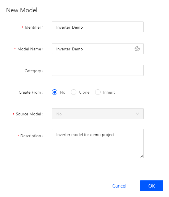
Click New Model, and provide the following settings in the New Model window:
- Identifier: Inverter_Demo
- Model Name: Inverter_Demo
- Model Name (en_US): Inverter_Demo
- Category: NA
- Create From: No
- Source Model: No
- Description: Inverter model for demo project
Click OK to complete the operation.
Click Edit, and click the Feature Definition tab in the Model Details screen.
Click Edit > Add > Create Custom Feature, and provide the following settings in the Add Feature pop-up window:
- Attribute 1
- Name: Inverter_Type
- Identifier: invType
- Data Type: enum
- Enum Items:
- Value = 0; Description = Central
- Value = 1; Description = String
- Required: Yes
- Attribute 2
- Name: Inverter_Capacity
- Identifier: capacity
- Data Type: float
- Unit: kWp
- Required: Yes
- Measurement Point
- Name: Active_Power
- Identifier: INV.GenActivePW
- Point Type: AI
- Data Type: double
- Unit: kW
- Service
- Name: Control
- Identifier: INV.Control
- Input Parameters:
- Parameter Name: control
- Identifier: control
- Data Type: enum
- Enum Items:
- Value = 0; Description = Stop
- Value = 1; Description = Start
- Output Parameters:
- Parameter Name: execResult
- Identifier: execResult
- Data Type: enum
- Enum Items:
- Value = 0; Description = Failure
- Value = 1; Description = Success
- Event
- Name: Error
- Identifier: Error
- Severity: Error
- Attribute 1
Click Publish to complete the operation.
For more information about models, see Creating a Model.
Step 2: Create a Product
Create a product called Inverter_Product. It is assumed that a device of this product model sends data in JSON format and the data transmission is not encrypted using the CA certificate.
In the EnOS Management Console, select Device Management > Products.
Click New Product, and provide the following settings in the New Product window:
- Product Name: Inverter_Product
- Asset Type: Device
- Device Model: Inverter_Demo
- Data Format: Json
- Certificate-based Two-way Authentication: Disabled
- Product Description: Inverter product for demo
Click OK to complete the operation.

For more information about products, see Creating Products.
Step 3: Register the Device
Create a device named INV001, which belongs to the Inverter_Product product model created in the previous step.
In the EnOS Management Console, select Device Management > Device Assets.
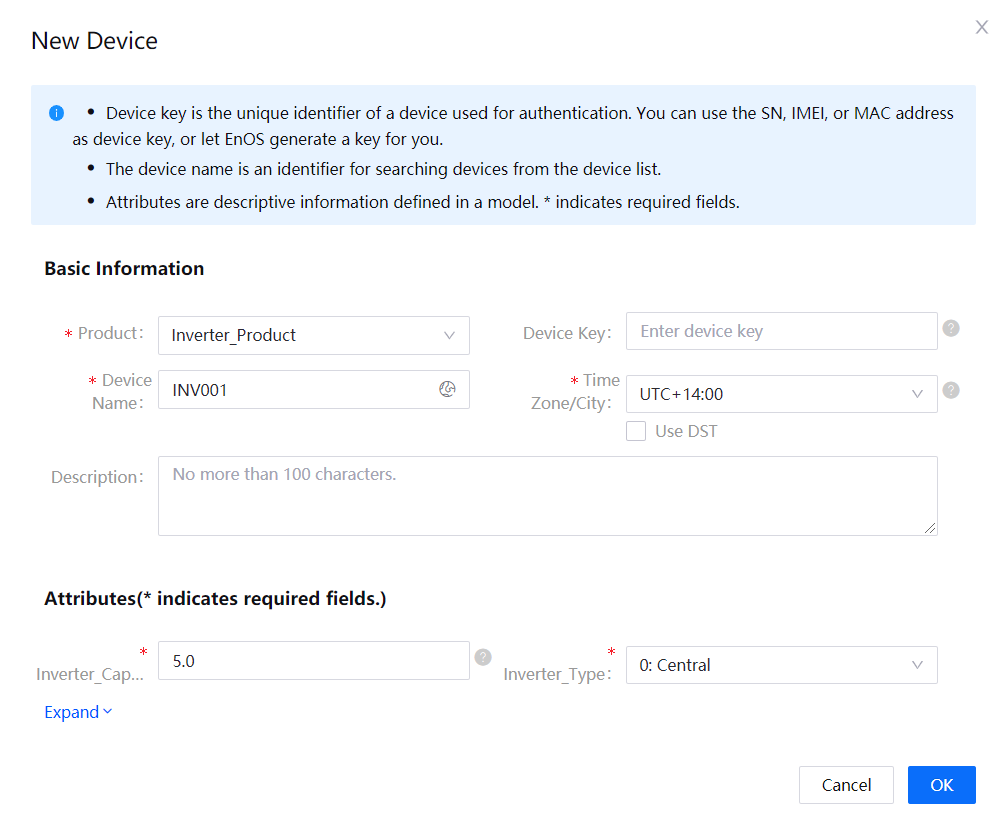
Click New Device, and provide the following settings in the New Device window:
- Product: Inverter_Product
- Device Name: INV001
- Device Key: Optional, generated automatically by the system
- timezone: UTC+14:00
- Use DST: Unchecked
- Inverter Capacity: 5.0
- Inverter Type: 0: Central (indicates a centralized inverter)
Click OK to complete the operation.
For more information about devices, see Creating a Device.
After you complete the device registration, obtain the device triple: ProductKey,DeviceKey,and DeviceSecret, which will be used in the following step.
Step 4: Configure the Storage Policy for the Measurement Point Data
After registering the device and before connecting the device to EnOS Cloud, you need to configure the storage policy for the data of the measurement point INV.GenActivePW. The detailed steps are as follows.
- If the Time Series Database resource has not been requested yet for the organization, log in to the EnOS Management Console, select Resource Management > Resource List, and request for the Time Series Database resource under the Enterprise Data Platform tab. For more information about requesting resources, see Resource Management on EnOS.
- In the EnOS Management Console, select Time Series Data Management > Storage Policies and configure the storage policy (with the appropriate storage type and storage time) for the measurement point data. For more information about configuring the storage policy, see Configuring TSDB Storage.
Step 5: Use Java SDK to Simulate the Device to Send Telemetry
Use the Java SDK sample code to simulate the sending of the inverter active power to the cloud as per the below.
Obtain the Device SDK. For information about how to set up the development environment, see the GitHub readme file.
Configure the EnOS Cloud connection as instructed in the readme file.
Configure the address of the EnOS cloud (
environment_address) and the device triple (ProductKey,DeviceKey, andDeviceSecret) into the sample connection program. The device triple is obtained when you register the device.Modify the
initWithCallbackmethod to establish connection between the device and the cloud.Modify the
postMeasurepointmethod to configure the name of the measurement point that sends telemetry to the cloud. In this example, we will set the active power point of the inverter, the point name INV.GenActivePW, and the corresponding point value.The following sample code is for connecting the device to EnOS and simulating the posting of data to the cloud:
import com.envisioniot.enos.iot_mqtt_sdk.core.ConnCallback;
import com.envisioniot.enos.iot_mqtt_sdk.core.MqttClient;
import com.envisioniot.enos.iot_mqtt_sdk.core.exception.EnvisionException;
import com.envisioniot.enos.iot_mqtt_sdk.message.upstream.tsl.MeasurepointPostRequest;
import com.envisioniot.enos.iot_mqtt_sdk.sample.SimpleSendReceive;

import java.util.Random;

public class demo1 {
    public static final String url = "tcp://{environment_address}";
    public static final String productKey = "ProductKey";
    public static final String deviceKey = "{DeviceKey}";
    public static final String deviceSecret = "{DeviceSecret}";
    private static MqttClient client;
    private static volatile boolean subDeviceLogined = false;
    private static Random random = new Random();
    private static int idInc = 20;
    private static final char[] HEX_CHAR = new char[]{'0', '1', '2', '3', '4', '5', '6', '7', '8', '9', 'a', 'b', 'c', 'd', 'e', 'f'};

    public demo() {
    }

    public static void main(String[] args) throws Exception {
        initWithCallback();
        postMeasurepoint();
    }

    public static void initWithCallback() {
        System.out.println("start connect with callback ... ");

        try {
            client = new MqttClient(url, productKey, deviceKey, deviceSecret);
            client.getProfile().setConnectionTimeout(60).setAutoReconnect(false);
            client.connect(new ConnCallback() {
                public void connectComplete(boolean reconnect) {
                    SimpleSendReceive.subDeviceLogin();
                    System.out.println("connect success");
                }

                public void connectLost(Throwable cause) {
                    System.out.println("onConnectLost");
                }

                public void connectFailed(Throwable cause) {
                    System.out.println("onConnectFailed : " + cause);
                }
            });
        } catch (Throwable var1)  {
        }

        System.out.println("connect result :" + client.isConnected());
    }

    public static void postMeasurepoint() {
        Random random = new Random();
        System.out.println("start post measurepoint ...");
        MeasurepointPostRequest request = (MeasurepointPostRequest)MeasurepointPostRequest.builder().addMeasurePoint("INV.GenActivePW", random.nextDouble()).build();

        try {
            client.fastPublish(request);
            System.out.println(" post measurepoint success...");
        } catch (Exception var3) {
            var3.printStackTrace();
        }
    }

}
Use the
handleServiceInvocation()method to handle the service invocation request from the cloud.public static void handleServiceInvocation() { IMessageHandler<ServiceInvocationCommand, ServiceInvocationReply> handler = new IMessageHandler<ServiceInvocationCommand, ServiceInvocationReply>() { public ServiceInvocationReply onMessage(ServiceInvocationCommand request, List<String> argList) throws Exception { System.out.println("rcvn async serevice invocation command" + request + " topic " + argList); return (ServiceInvocationReply)ServiceInvocationReply.builder().addOutputData("execResult", 0).build(); } }; client.setArrivedMsgHandler(ServiceInvocationCommand.class, handler); }
For more information, see Using the EnOS Device SDK.
Step 6: Check the Device Connection Status
In the EnOS Management Console, click Device Management > Device Assets, locate the device, and check the status of the INV001 device and confirm that the device is Online.

Step 7: View the Device Data
- From the device list, locate the device and click the View icon to show the Device Details page.
- Click the Measurment Points tab, find the INV.GenActivePW measurment point, and click the View Data icon to open the Data Insights page.
- View the latest data of the measurement point on the Data Insights page. If the TSDB storage policy has been configured for the measurment point, you can also view the historic data of the measurment point in a chart or table. For more information about data insights, see Generating Time Series Data Chart.
Step 8: Use the Online Debugging Tool to Set the Measurement Point Value
Click Device Management > Products, and click the View icon for the product that the device belongs to.
In the product details page, click the Debugging tab。
Select the device to debug.
Select the measurement point from the Debugging drop-down list and the Method to use. In this example, we will select the INV.GenActivePW for the measurement point, and the method as Set, and click Run.
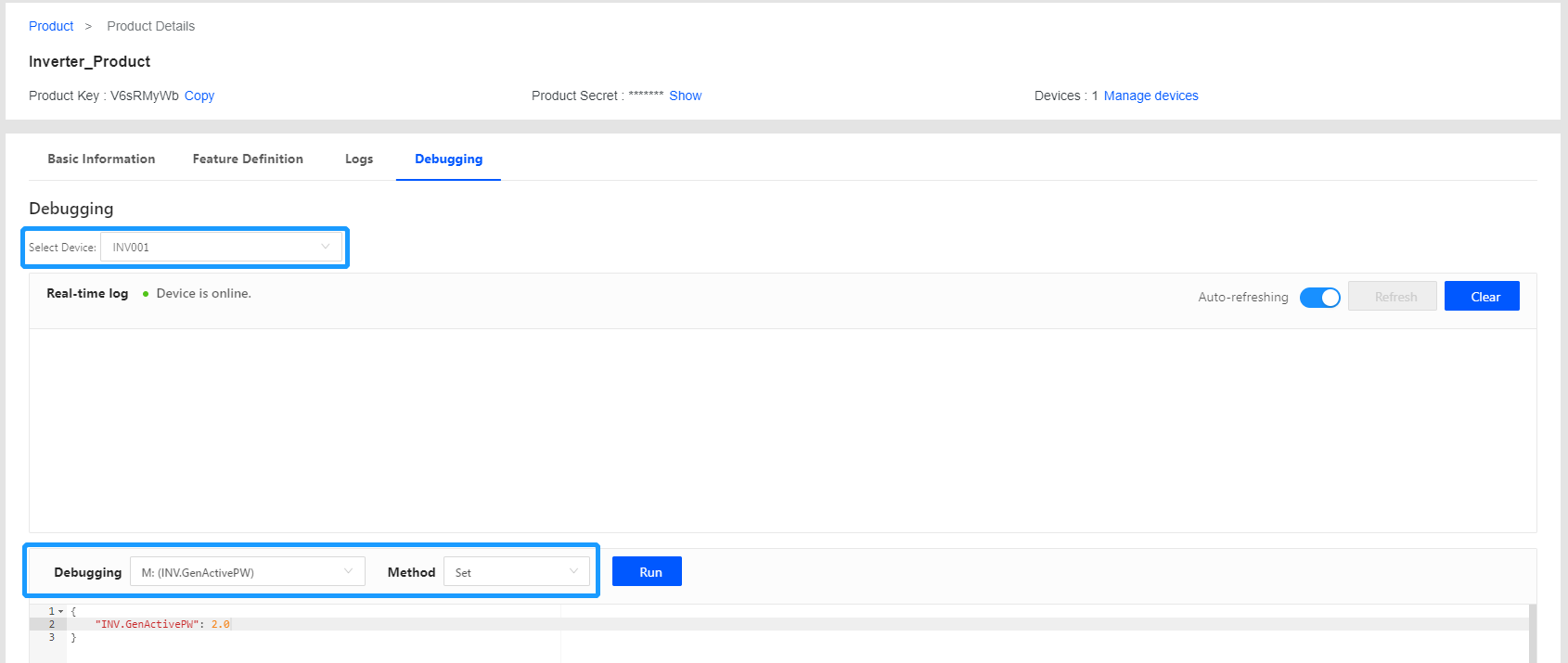
When the value of the measurement point is set successfully, you will receive a response similar to the following from your Java development environment:
AnswerableMessageBody{id='21', method='thing.service.measurepoint.set', version='1.0', params={INV.GenActivePW=2.0}}