Tutorial: Connecting a Simulated Meter to EnOS Edge via IEC104 Protocol
This guide describes how to connect the Edge IIoT Gateway device to the cloud for Edge delivery engineers and third-party partners. Take the electricity meter as an example.
Before You Start
Make sure that you have created and connected Edge gateway assets in the EnOS Management Console. For more information, see Registering Edge Gateway Device.
Step 1: Register Device to EnOS
Define a Private Model
Log in to EnOS Management Console, and select Models to open the Model page.
Go to the Private page. Click the New Model and provide the following information:
- Identifier: Meter_for_tutorial
- Model Name: Meter_for_tutorial
- Created From: No
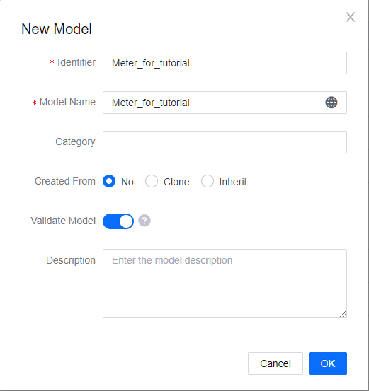
Click OK to save the basic information of the private model.
From the list of created models, find the model that needs feature definition and click the view button
 .
.Click the Feature Definition tab and click Edit > Add > Create Custom Feature.
Provide the following information in the pop-up window to create features for 4 measurement points. The 4 measurement points that you created represent Ua, active power, reactive power and Ia for the electricity meter
Measurement Point Feature Type Name Identifier Point Type Data Type Unit Quality Indicator 1 Measurement Points Ua Meter.Ua AI double Electric Potential: volt | V No 2 Measurement Points P Meter.ActivePower AI double Power: kilowatt | kW No 3 Measurement Points Q Meter.ReactivePower AI double Power: KiloVolt Ampere Reactive | kVar No 4 Measurement Points Ia Meter.Ia AI double Electric Current: ampere | A No Click Confirm. Click Publish at the bottom of this page.
Create a Product
- In the EnOS Management Console, select Device Management > Products.
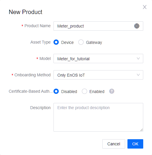
- Click New Product, and provide the following information in the New Product window.
- Product Name: Meter_product
- Asset Type: Device
- Model: Meter_for_tutorial
- Onboarding Method: Only EnOS IoT
- Certificate-Based Authentication: Disabled
- Click OK to save the configuration.
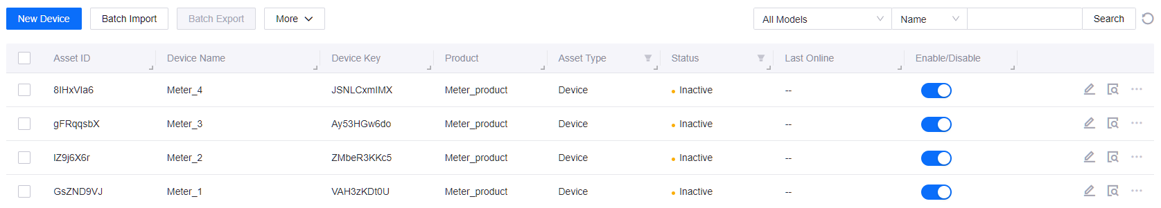
Register a Device
- In the EnOS Management Console, select Device Management > Device Assets.
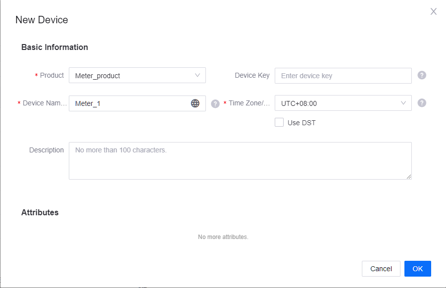
- Click New Device, and provide the following information in the New Device window.
- Product: Meter_product
- Device Name: Meter_1
- Timezone/City: UTC+08:00
- Click OK to save the configuration.
In this step, you need to create the following 4 meters:
Step 2: Configure a Template to Map Data Points
A device template maps data collected from a device to the model measurement points defined on EnOS Cloud using a protocol.
For more information about flexible template configuration In EnOS Edge, see Access Templates.
Create a Template
- In the EnOS Management Console, select EnOS Edge > Template > Private Template.
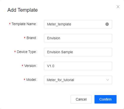
- Click New Template, and provide the following information in the Add Template window.
- Template Name: Meter_template
- Brand: Envision
- Device Type: Envision sample
- Version: v1.0
- Model: Meter_for_tutorial
- Click Confirm to save the configuration.
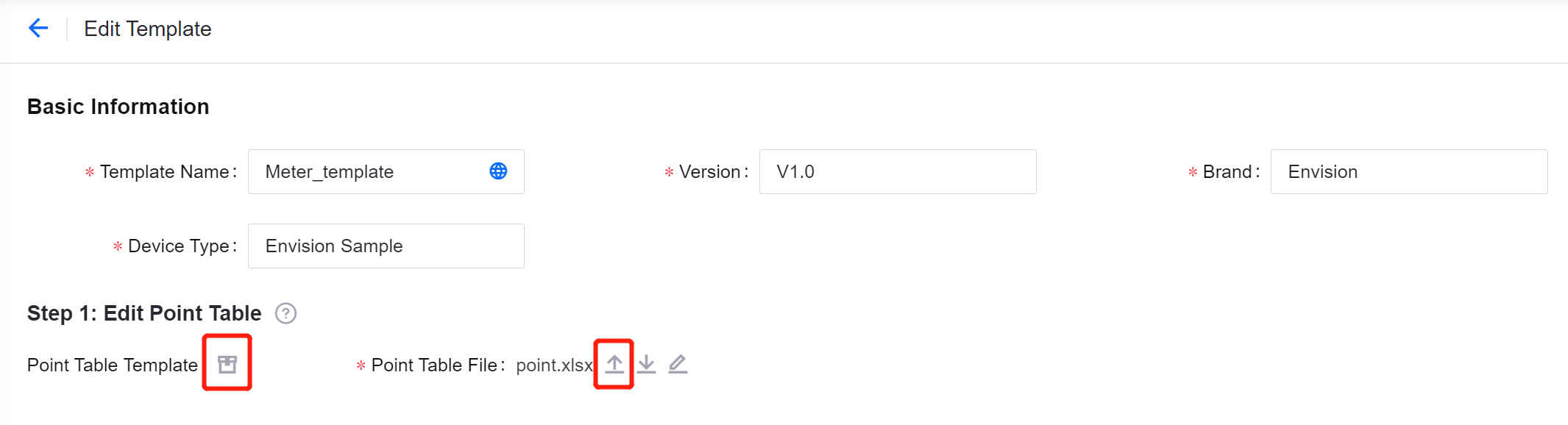
Edit a Template
Click the
 to enter the Edit Template page of the template that you just created.
In the “Step 1: Edit Point Table”, click the
 and go to the Public Protocol tab.
Search for the IEC104_Gateway_X86 protocol and click the download button to download its standard point file (point.xlsx).
Download
Original_Point_Info_en.xlsxand double-click it. As shown below, each meter has the same set of measurement points to collect data including Ua, Ia,, active power, and reactive power. Thus, you can determine to map the data in the same access template.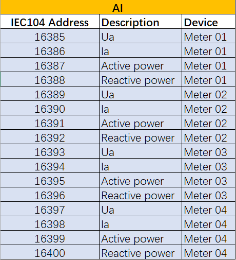
Double-click the standard point file (point.xlsx).
Fill in the following information on the point sheet of the point file .
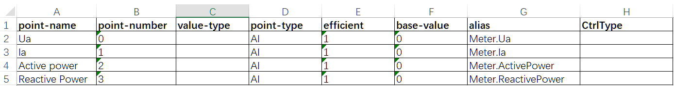
- In actual scenario, you need to fill in the point sheet according to the Readme sheet of the point file and the description row of original device point table (Original_Point_Info.xlsx).
- You can fill in identifiers of meter model points in the alias column for Auto-mapping. This step is a prerequisite to enable the Auto-mapping function.
Back to the Edit Template page and click the upload button to upload the edited point file (point.xlsx) under the “Step 1: Edit Point Table” session.
Click Auto-mapping under the “Step 2: Map Model Point” to map device measurement points to model measurement points.
(Optional) Auto-mapping function only supports EQUAL mapping. If you need to use other formulas, click the Mapping Points
 of the measurement point. In the Collect tab, click Add Formula and select the formula. See Point Mapping Formulas.
Click Save to save the configuration.
Step 3: Configure Connectivity Information
Add a Connection
In the EnOS Management Console, go to EnOS Edge > Edge Management.
Click the view button
of the target Edge device to go to the Edge Details page.Go to the Access > Ethernet tab and click
 to add a connection.
Provide the following information in the Add Connection window:
- Connection Name: Connection_for_tutorial
- Connection Mode: TCP/IP Client
- Primary Interface: The IPv4 address of your laptop. For port, you can give it a random integer greater than or equal to 1000.
- Protocol Type: IEC104
- Protocol Version: No action is required. But you might have to modify the configuration if you use other protocols or as needed.
Click Confirm to save the configuration.

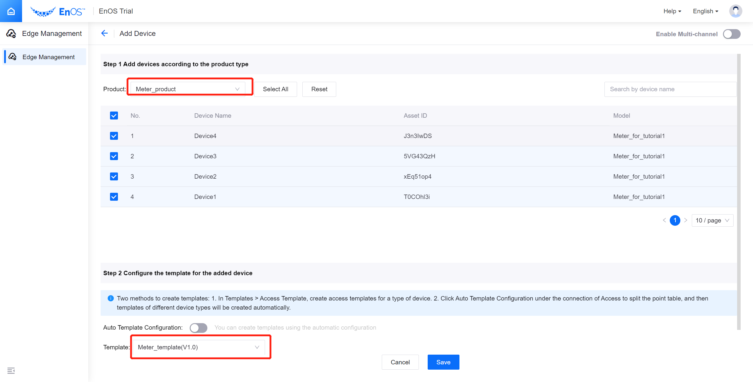
Add a Device
- In Access > Ethernet tab, click to expand the connection you just created and click New Device.
- Under the “Step 1: Edit Point Table” in the Add Device window, select the product Meter_product we just created and check the devices Meter_1, Meter_2, Meter_3, and Meter_4.
- Under ”Step 2: Map Model Point”, select the template Meter_for_tutorial.
- Click Save to save the configuration.
Edit the Offset Range for Devices
You need to edit the offset range for each device to calculate the information body address of each measurement point. And then the system can collect the data from the corresponding address bits.
Calculation Method: [Information body address] = [Information body start address] + [Offset]. (The information body address bit of the AI measurement point starts from 16385.)
- Go to Access > Ethernet tab and click to expand the connection you created.
- Click the view button of the device to go to the Edit Device window.
- Enter the logical address and AI offset according to the original point table (Original_Point_Info.xlsx).
The offset configuration items for this tutorial are shown in the following table:
| AI measurement point | AI offset | Logical address |
|---|---|---|
| Meter_1 | 0-3 | 1 |
| Meter_2 | 4-7 | 2 |
| Meter_3 | 8-11 | 3 |
| Meter_4 | 12-15 | 4 |
Publish Edge
Click Publish to distribute the configured resource package to the Edge devices.
Step 4: Simulate Data using the Protocol Simulator
Configure the Protocol Simulator
Use a protocol simulator to simulate and send data to the cloud. For more information, contact the Edge Team (edge-support@univers.com).
View the Simulation Data in EnOS Management Console
- In the EnOS Management Console, go to EnOS Edge > Edge Management.
- Click the view button of the target Edge device to go to the Edge Details page.
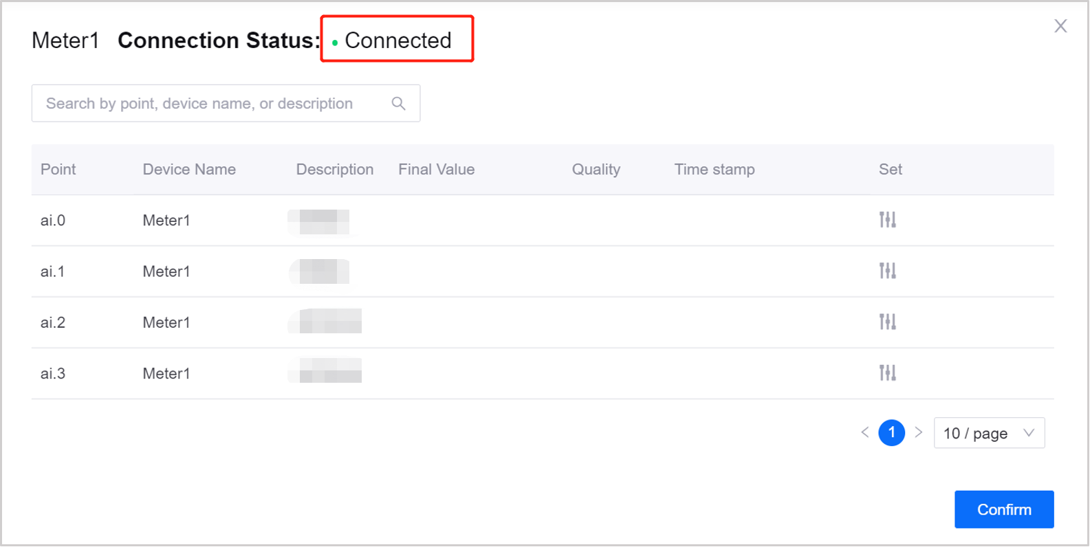
- In Access > Ethernet tab, click to expand the connection created before.
- Click the view button of the sub-device. When the connection status of the sub-devices is Connected, the data are connected to the cloud.